Breadboards 101
This is a topic that’s probably been covered a bajillion times (better than me) elsewhere on the internet. There’s nothing special about a breadboard; it is used for connecting wires without the need to solder. The ‘holes’ are connected, ‘under the hood’, they are actually just rows and rows of metal rails. So you plug a wire into a hole, and that wire connects to every other hole on that rail. I’ve added some dodgy red, green, yellow and blue squares to this image in MS Paint to demonstrate how the rails are grouped:
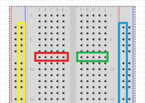
The two ‘outer columns’ (yellow and blue squares in my diagram) are rails that run from the top to the bottom of the board (called the ‘bus strips’). Then the inner holes (red and green squares) are grouped in rows of five (called ‘terminal strips’), separated by a chasm in the middle (the ‘centerline’).
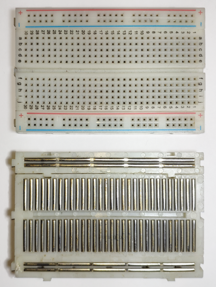
The Wikipedia page on breadboards has this image, which perfectly demonstrates the concept of how it works and how the rails are connected:
GPIO and the Pi Pico
The Pico has a-lot of pins- (40 in-fact!); but we’re only using six of them for our circuit.
Searching for “Pi Pico Pinout” will garner the following diagram:

When I saw this as a beginner; I was ready to pack it in.
What does it all this stuff mean? The short answer is: Most of it doesn’t matter. Don’t worry about it.
The ‘GPIO’ in ‘’GPIO Pins” (this kind of pin-interface we are using), stands for “General Purpose Input Output System”. The key there is General Purpose. See how most of the pins in the diagram above have a green label next to them, with “GP0, GP1, GP2…” and so forth? These are our ‘general purpose’ pins. We get 26 of those (they are numbered up to ‘28’ but don’t let that distract you). All the other coloured labels (like UART, SPI, I2C, ADC and so-forth) are pins that support special additional protocols that we can totally ignore for this project. If we were wiring up an OLED screen- we may have to use the I2C pins, and if we were measuring the voltage value of something- we might be using the ADC pins… But we’re not doing any of those things so just forget about it for now.
26 general purpose pins, each labelled and numbered in the diagram above (light green labels).
Then you’ll notice there’s 8 pins labelled “GND” in black; those are ‘ground’ pins. All the ground pins are connected to each other (to form a ‘ground plane’) Components connected to the Pico should always also be connected to this ground plane (just electronics things).
The other must-see here are the pins labelled in red. These are the ‘power’ pins. Be careful with the power pins. You won’t zap yourself or blow up your home or whatever- but you can potentially damage the Pi Pico itself if you wire these pins up wrong. That being said; I’ve wired them up wrong many times and am yet to blow a circuit, so the stakes are pretty low.
- VBUS – This pin ‘passes on’ the 5-volts of power supplied to the Pico via the micro-USB cable. So if you have something that requires USB power to function; you can ‘bus’ power to it via the Pico using this pin. Our project doesn’t need 5 whole volts, but if we did use it; the components could “probably” handle it without posing any kind of hazard.
- VSYS – This pin ‘takes in’ 5-volts; to power the Pico system itself without the need for a USB cable. Theoretically, you could wire up some sort of battery to this pin and make whatever device you are creating ‘portable’. We don’t need to worry about VSYS for this project, because we’re going to power the Pico using the USB connection.
- 3V3 (OUT) – This pin is what we’ll be focusing on. Most small electronic components (the rotary encoder in this project, for example) run on 3.3 volts, and thus the Pico supplies 3.3 volts of power through this pin.
So by this point you may have guessed that you’ll be referring to the diagram that labels all the pins quite a bit. Here’s the official data sheet, you may want to print it.
Making the circuit
First of all, make sure the Pico isn’t plugged into the computer for some reason (there’s no power going through it- blah blah blah).
The Ground
Let’s do the ground wires. We’re going to make use of the long ‘bus strips’ on the outer edge of the breadboard. By connecting a GND pin; in this case- pin 38 (third pin down on the right-side of the Pico); to one of the bus strips of the breadboard, we extend the grounding to that strip, making it easy to ground other components further down the board.
Most breadboards will have thin red and blue lines printed next to the bus strips as a visual aid. There’s nothing different about these rails on the breadboard, but follow convention to avoid confusion, and wire the GND pin to the ‘blue’ bus strip.
We only have two components for this project; a button- and a rotary encoder. The encoder probably has a pin that is labelled as ‘GND’, so it’s a no brainer. Connect the GND pin of the encoder, to the ‘blue’ bus-strip on the breadboard.
The button is a little less obvious. It should ‘straddle’ the centreline of the breadboard, so that two of the button’s pins are connected to one side of the breadboard, and the opposite two on are on the other. Connect one of the button’s pins to the ground (that ‘blue’ bus strip).
The Button
With the button attached to ground on one side, we’ve only got one more connection to make to finish it off. Connect a pin on the opposite side of the button (I like to use the one that is diagonally opposite) to one of the general-purpose pins of the Pico. Let’s go with GP15 (pin #20, furthest one down on the left side of the Pico) because it’s closest.
Elsewhere on the internet- you may see people integrating ‘pull up’ or ‘pull down’ resistors into their circuits when wiring up buttons. The Pi Pico has internal resistors that will prevent any horrible short circuits from happening, and this is meant to be as simple a project as possible; so don’t worry about it! It’ll be fine without extra resistors.
The Encoder
Now we’ve just got the 4 remaining pins of the rotary encoder to wire up. This is easy- one of the pins will be probably be labelled ‘+’. We want to connect that one to the 3V3 power pin on the Pico (Pin #36- 5th down on the right side). You can either connect it directly from the Pico to the rotary encoder, or make use of the other, ‘red’ bus strip on the breadboard (like what we’ve done with GND).
Then there’s the SW, DT and CLK pins:
- The ‘SW’ pin means “Switch”. This is the output of the push-button. When you push the rotary encoder ‘knob’, the voltage of this pin goes to a logical value of ‘LOW’.
- The ‘DT’ and ‘CLK’ pins are… well… if you want to know how the actual encoder works, look up “quadrature encoding**”.** In short**,** there are two pulse-waves (one on each of these pins), and by determining the amount of offset between those two waves- with a bit of programming logic, we can determine when the encoder is rotated, and in what direction.
These three remaining pins can be attached to any of the remaining ‘general purpose’ pins on the Pi Pico. Let’s use GP12 for CLK, GP13 for DT, and GP14 for SW.
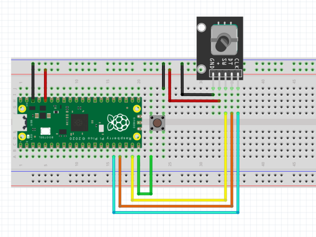
Overall, you should have something like this:
| Button | Pi Pico |
|---|---|
| One Side | GND |
| Other Side | GP15 |
| Encoder | Pi Pico |
|---|---|
| GND | GND |
| + | 3V3 (OUT) |
| SW | GP14 |
| DT | GP13 |
| CLK | GP12 |
Now that everything is all wired up- we can move on to programming the Pico.